February 2011 Archives

nexus one, piecemeal

| No Comments | No TrackBacks
 

NOT AGAIN :(


Ergh.  Broken Screen on the google N1.  Waiting for a new Synaptics digitizer (the touchscreen) for my phone.  Hope I can scramble it back together!

UPDATE: it works, perfectly!
...just $40 dollars and an hour of meticulous time...

Enhanced by Zemanta


Light to Frequency toy/noise generator

| No Comments | No TrackBacks

...getting it in the box was easy.  the hard part was getting it into the box!


I've been obsessed with TSL230R-LF programmable light to frequency converters; many have been burnt up by these hands.  They're commonly available, cheap and if you like making music/noise, then wiring them up is a snap (even compared to making a 555 generator).    

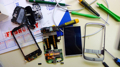
There are two TSL230R-LF in the blue box (recessed below the black holes), and and an Arduino micro-controller for simple 
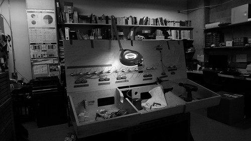
syncopation.  The box pictured above is wire-wrapped with a 24 pin header connecting the board to the controls.  When plugged in, the box produces super clean digital 
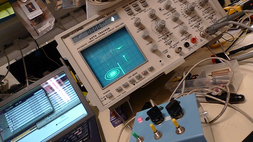
square-waves based on the intensity of light.  You can simulate 8-bit acceleration in spy hunter, create noisy beats, or control it like an optical theremin with a very full audio range.  The switches control the sensitivity and the pots control the syncopation.  The led's are a direct indicator of when the LTFC is generating a pulse.   The output is to a stereo mini 3.5mm jack with one generator to a channel i.e left and right.   On the oscilloscope, the two outputs have been plotted in XY mode to create the spiral.  

The arduino code is very simple; two pins are set to analog read, the value is then translated to on/off pulses with digital write and sent via two pins to the LTFC enable/disable pin.  If you can't tell, I almost always start with an arduino example and build onto it for ease...in this case there are some erroneous lines of code as bonus!

After I get the PCB back (and working!), I'll post that, for now, here's a schematic and code:


ltf1.jpg
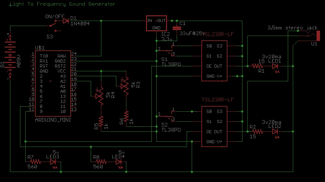
p.s.  The schematic is missing a 120 ohm resistor at the ground of the 3.5mm jack.  This will allow for the LED's to remain on when plugged into anything with a coil (i.e. headphones, speaker, etc).  Also, when the battery drops below 5 volts, the 5 volt based Arduino will stop working, whereas the LTFCs, which are tied to a 3 volt regulator, will continue to function.  This could be solved by using the 3.3 volt Arduino pro mini.  And maybe, there will be a version two.

------
//fun trick noisemaker, syncopator, tc 2010


int sensorPin = 3;
int sensorPin2 = 2; // select the input pin for the potentiometer
int ledPin = 9;   // select the pin for the LED
int ledPin2 = 8;
int sensorValue = 0;  // variable to store the value coming from the sensor
int sensorValue2 = 0;
int x = 100;
int x2 = 100;
int y = 0;
int y2 = 0;
float z = .255;
int pwm = 0;
void setup() {
  // declare the ledPin as an OUTPUT:
  pinMode(ledPin, OUTPUT);  
  pinMode(ledPin2, OUTPUT);
    Serial.begin(9600); 
}

void loop() {
  // read the value from the sensor:
  sensorValue = analogRead(sensorPin);    
  sensorValue2 = analogRead(sensorPin2);    
  delay(100);
  // turn the ledPin on
 // digitalWrite(ledPin, HIGH);  
  // stop the program for <sensorValue> milliseconds:
  Serial.println(sensorValue);
  Serial.println(sensorValue2);


 if(sensorValue < 670 && sensorValue > 65)
 {
      //pwm = z*sensorValue;
      //Serial.println(pwm);
      //analogWrite(ledPin,pwm);
      Serial.println("yes!");
      y = sensorValue/3;
      digitalWrite(ledPin,HIGH);
      delay(y);
      digitalWrite(ledPin,LOW);
 
 
 }
 
 
 else if (sensorValue > 670)
  {
    digitalWrite(ledPin, LOW);
    
  }
 else
 {
   digitalWrite(ledPin,LOW);
 
      
  }
  
 
 if(sensorValue2 < 670 && sensorValue2 > 65)
 {
      //pwm = z*sensorValue;
      //Serial.println(pwm);
      //analogWrite(ledPin,pwm);
      Serial.println("yestwo!");
      y2 = sensorValue/3;
      digitalWrite(ledPin2,HIGH);
      delay(y2);
      digitalWrite(ledPin2,LOW);
  }
 
 
 else if (sensorValue2 > 670)
  {
      digitalWrite(ledPin2, LOW);
     
      
  }
 else
 {
   digitalWrite(ledPin2,LOW);
      
  }
  
                  
}

Enhanced by Zemanta

3 computers, 1 console: sync'd HD playback.

| No Comments | No TrackBacks
 

the internal wiring of the console in progress...


This was a glacial project, fraught with loose ends.  There was to be a 16 button interface console, all with feedback, controlling 3 sync'd HD video servers.  Well, once again, we turned mac minis into servers...

ISSUE 1:  Memory leak! 

The beta application would crash hours after launching.  As standard protocol, i tweaked the code and assumed that i was debugging ID10T errors.  But as time went by, it was clear that the app was sucking up ram with each new movie--never clearing out the memory.  The jitter object responsible was jit.qt.movie--specifically with direct to window playback.    Fortunately, the people at Cycling '74 are super awesome.  I posted a test patch as proof of a memory leak, which was then quickly confirmed by the developers.  They provided me a work around, and then we were on our way.  As for max/msp/jitter, the next revision eliminated this bug.

ISSUE 2: Erratic Triggering!

The Phidgets 0/16/16 I/O board was not playing well.  Everytime the status of one button would change, it would send a quick hit to the rest of the buttons, even though the input led's for those buttons remained off!   In effect, a debounce structure had to be built in.  i suppose its not really an issue.  standard fare.  though, getting this structure built involved the phidgets object crashing max/msp endlessly.  

grab1.tif
an rudimentary incorrect sync calculation

ISSUE 3:  No sync!

The content was delivered in several releases.  All were encoded differently.  This severely effected the quality of sync as the movies all had differing time bases.  Two identical movies may have had the same fps and duration, but QT would see one as slightly longer than the other.   i ended up re-writing the control structure in the midnight pre-release hours--adding a udp sync pulse with one machine as master and the other two as slaves.  It probably should have been done this way from the beginning, but in my dev tests, everything worked perfectly without it.  But in the tests, the content was encoded uniformly.

The rest:

Wiring up the console was really fun!  It may seem humdrum, but the task of terminating a whole mess of cable in a logical fashion is rather relaxing; it gives a sense of craftsmanship.  No soldering on this job, all crimping and terminals.  The main cabling itself is also done in telecom-style wire-harness lacing.  This is elegant, better for the environment and less likely to induce zip-tie cuts on the hands.  As this project was mostly finished, then mothballed, then brought back out, i was sure happy that all of the wires were labeled correctly when it came time to terminate them into the main board.  always label everything!

The hap buttons contain old school lamp bulbs.  The buttons are disabled when the initial selection is made by killing the sample rate to the phidgets board.  The supply voltage is also killed as a double redundancy lockout to prevent anyone from "confusing the system."  They blink when the selected video is playing and get slightly warm.  In total, the buttons draw around 4 amps of current; future plans involve swapping in low-current LED's to reduce load, heat, etc.

The triggers are distributed to the minis via the built in network service of the phidgets max/msp object.  

The audio, eh, whatever.  standard stuff:  3 unbalanced & summed signals passed through a compressor and then to a networked amplifier.

Lastly, and isn't it always the case, i would do this differently if I were to do it again!


Enhanced by Zemanta

About this Archive

This page is an archive of entries from February 2011 listed from newest to oldest.

January 2011 is the previous archive.

March 2011 is the next archive.

Find recent content on the main index or look in the archives to find all content.